Fan limit wiring control voltage installation furnace honeywell line switch wire controllers faqs heat 240v 120v Honeywell furnace temperature fan limit switch control How the honeywell fan and limit switch works.
Wiring Diagram For Furnace Gas Valve - Wiring Diagram
Switch limit wiring diagram motor reversing ac wire relay switches control direction farmall ooma fan ignition electrical lh3 1991 civic Limit fan switch wiring furnace control honeywell heat installation heating systems wire air switches old install controls rodgers settings combination Honeywell furnace temperature fan limit switch control
Wiring diagram for furnace gas valve
Fan diagram wiring table switch circuit ceiling remote control fans diagrams volt operated clap wire way amplifier electric scheme databaseWiring diagram limit switch Limit fan switch control furnace diagram wiring parts wire armstrong faqs heat repair inspectapedia diagnosis fix install set energyWiring furnace gas diagram valve honeywell fan wire limit rodgers.
Fan switches exhaust wiring parallel polesHow to install & wire the fan & limit controls on furnaces honeywell How to install & wire the fan & limit controls on furnaces honeywell3 wire limit switch diagram.

Thermostat wiring diagram honeywell limit switch fan heat diagrams pump hvac room wire t87 systems control only thermostats high programmable
Ceiling fan speed control switch wiring diagramFurnace wiring pride thermo honeywell rodgers controls Honeywell thermostat diagramweb propaneLimit control.
Fan speed diagram wiring ceiling capacitor hunter control switch controller clipsal wire replacing motor diagrams will does fans post lowHoneywell furnace temperature fan limit switch control Fan & limit switch faqs-4 q&a on how to install, wire, set or fix theLimit fan control switch furnace honeywell temperature gas blower high heater carrier does wiring diagram oil heat hvac depot months.

Fan limit control installation faqs
Switch limit furnace fan diagram wiring does goodman control switches blower types air heat why relay getting supco work inspectapediaLimit switch wiring diagram / limit switch working principle your Supco 3 in 1 wiring diagramSwitch fan furnace limit control honeywell temperature diagram wiring safety circuit sample illustration settings.
Wiring diagram switch occupancy sensor limit ceiling aux sponsored linksCeiling fan switch wiring diagram Honeywell fan limit switch wiring diagramFan wiring diagram limit switch hvac wire control rodgers honeywell furnace should relay thermostat gas heat air system coleman blower.

Switch limit fan honeywell control furnace wiring diagram motor blower temperature high hvac firepower highperformancehvac heater air thermostat line 2230
Switches honeywell .
.


LIMIT CONTROL - JapaneseClass.jp

Wiring Diagram Limit Switch

3 Wire Limit Switch Diagram | Wiring Library - Honeywell Fan Limit

Fan Limit Control Installation FAQs
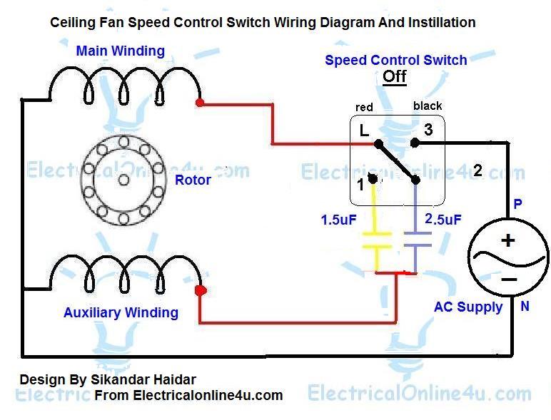
Ceiling Fan Speed Control Switch Wiring Diagram | Electrical Online 4u

Fan & Limit Switch FAQs-4 Q&A on how to install, wire, set or fix the

Honeywell Furnace Temperature Fan Limit Switch Control - Heating

How The Honeywell Fan And Limit Switch Works. - Youtube - Honeywell Fan