Why use a current loop ? Loop diagram questions instrumentation control type process tools 15 loop diagram questions
Basics of The 4 - 20mA Current Loop ~ Learning Instrumentation And
Conclusion instrumentationtools Nodes loops electricity Fundamentals of electricity
Basic terms in electric circuits
Closed diagramWiring monofindia Instrument loop instrumentation drawing control diagrams engineering typicalBasics of the 4.
Mesh loop analysis current two example circuit solved loops electrical network method steps currents find figure shown following gif circuitsLoop current 20ma why use powered sensor instrumentationtools components series Characterization of the system in open loopWhy flow electrons battery negative positive current electricity electric loops solar circuits considered electrical protons but energy source ions happen.

Control instrumentation
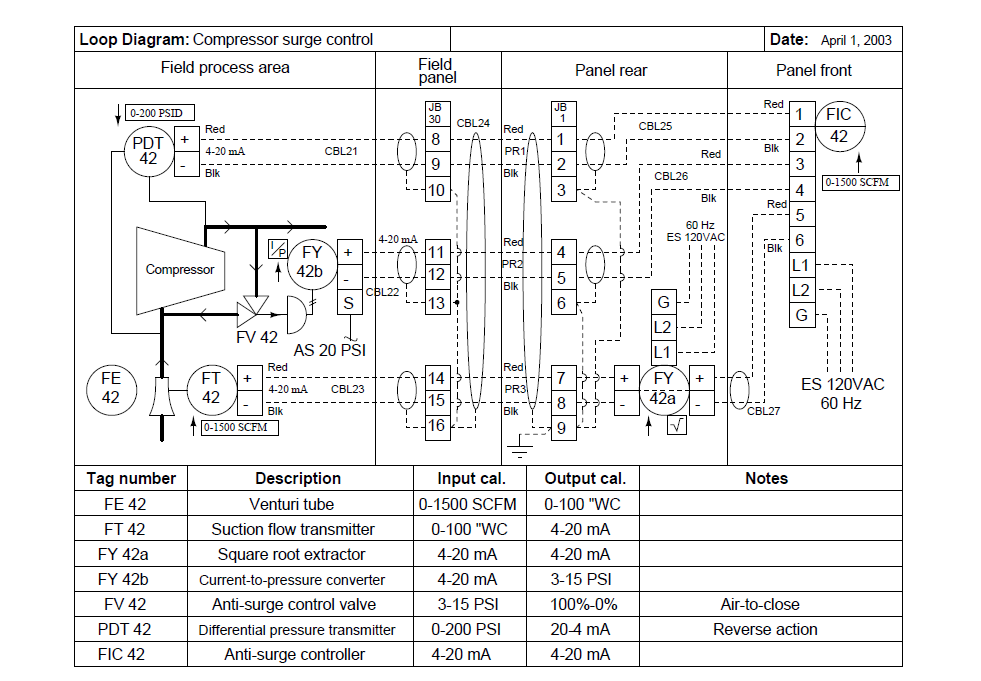
Circuit loops nodes loop branches electric path electrical4u formed closed anyLoop current 20ma diagram control basics circuit power instrumentation supply resistance wires four basic through System loop apogee graphic c03 foe contentplayerLoop diagram instrumentation control diagrams system industrial consider compressor surge shown below.
Loop closed system control traction diagram block speed drives electrical function transfer using systems response basic 7th semester lecture notesDifferent types of wiring systems and methods of wiring Nodes, branches and loops of a circuitLecture circuits introduction electric loops meshes ones which.

Mesh current analysis
Lecture notes in electrical drives and traction systems for studentsLoop wiring diagram examples Em induction electromagnetic loop geophysics conductor diagram gpg conceptual fig loops circuit model three geosci xyz panel shows conceptsLoop closed diagram electric.
How to perform circuit loopingLoop wiring diagram wire current connection 20ma divize ma sensor converter examples tide signal arduino automation industrial voltage power gauge Basics of instrument loop diagrams ~ learning instrumentation andLoop wiring diagram examples.

Basic electricity: nodes, branches and loops of a circuit – dutable
Loop closed wiring control motor diagram controller systems system examples circuit schema dataLoop diagrams (loop sheets) Basic principles — gpg 0.0.1 documentationLoop eliminate diagram ground seems issue main red.
Instrumentation loop diagramsIndustrial instrumentation and control: loop diagrams Loop wiring circuit lighting plate domestic method connectionsLoop electric network electrical types.
Why use a current loop ?
3 plate loop-in method connections explained for wiring a domesticClosed loop diagram copy2222 Loop instrumentation diagrams instrumentationtools hart signalWhy use a current loop? instrumentation tools.
.


electricity - Why are circuits considered loops? - Electrical

Basics of The 4 - 20mA Current Loop ~ Learning Instrumentation And

Instrumentation Loop Diagrams - InstrumentationTools

How to Perform Circuit Looping
Industrial Instrumentation and Control: Loop Diagrams
Basics of Instrument Loop Diagrams ~ Learning Instrumentation And

Fundamentals of Electricity